自行车发电机
标签:DIY 发电机 自行车
MuggleV 发布于 2015-06-26 16:48
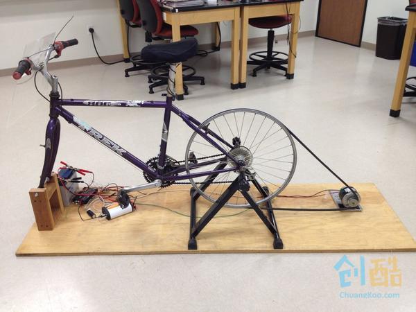
原文:http://www.instructables.com/id/DIY-Bike-Generator
作者:SKSW47
作者计划把这辆车放在学生活动中心,可以当做电源使用,想给笔记本、手机充电,上去踩个几分钟就行了,怎么样,方便吧,还能锻炼身体~
组装方法大致如下:自行车后轮通过皮带绑到直流电机上,电机连到充电控制器,控制器给蓄电池充电,电池连到逆变器,然后就可以把手机插到逆变器的插座上了。
材料(必需):
Step 1: 固定自行车架
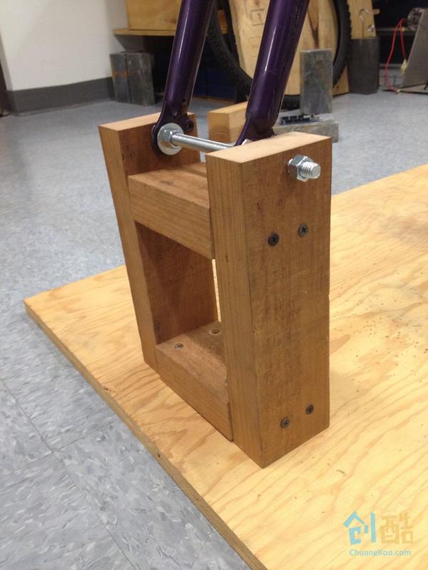
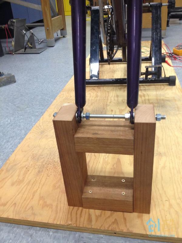
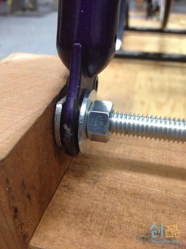
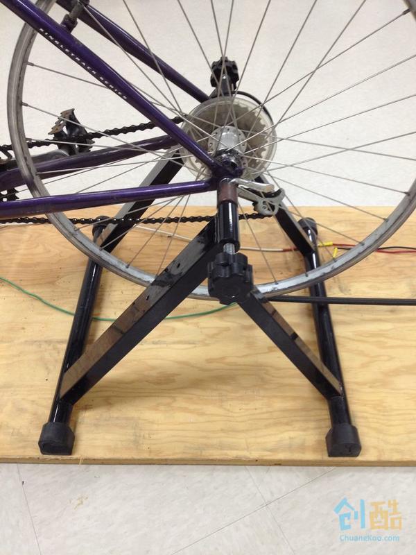
把自行车架在胶合板上,后轮用自行车支架固定,确保整个车体稳固地架在木板上。
Step 2: 连接皮带轮和电机
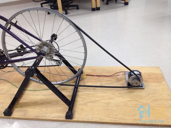
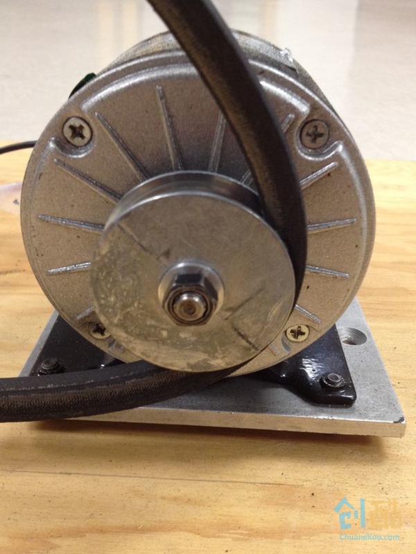
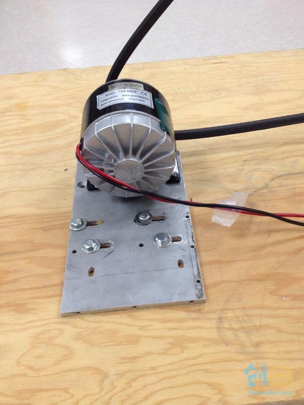
进行这一步之前先把车轮胎剥掉。剥轮胎技巧看这里:不用工具,如何徒手剥轮胎?(记得先把车胎的气排干净)
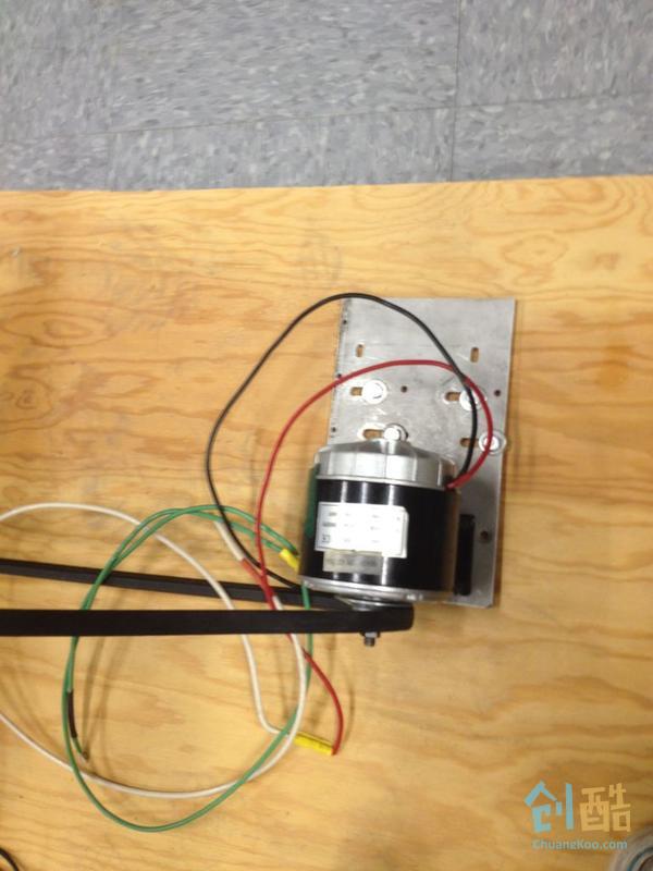
接下来用D型圈把皮带轮固定到电机上。因为电机伸出来的那部分是D型的,这样固定后皮带轮就能顺利带动电机的机芯转动。用于固定的螺钉是左手螺旋的,刚好和电机转动方向相反,这样不会出现螺丝慢慢松动的情况。然后就是连接车轮和皮带轮,这里要确保两个轮处于同一平面上,而且要使皮带尽可能拉紧。
Step 3: 关于皮带的选择
电机的额定速率是2800rpm,假设我们骑车速度为30Km/h,算下来后轮的速率为250rpm左右。这样的话,我们需要选择一个直径为车轮1/10左右的皮带轮。考虑到耐用性,我们选择了最厚的皮带。
Step 4: 连接电机和充电器
充电控制器用于调节流过电池的电流,防止电池过充或者过放。过充会导致电池里的水电解成氢气和氧气,从而硫酸浓度增加,电镀氧化,使得电池快速老化。而过放会导致硫化,使硫附着在电镀上,硫酸浓度下降,电池将无法充电到想要的电压。
这个充电器能够调节流入电池的电流,踩自行车时能读出当前产生了多大电压,还有在踩自行车这段时间内总共产生了多少电能。它没法显示当前电池还有多少剩余电量,因此我们给使用者做了些限制,必需至少踩多长时间才能开始充电。
我们选用的是12V的电池,因此充电控制器需要提供12V~24V的电压。电池的最大充电电流为5.4A,充电器也需要限制其输出电流在这个值以下。充电器电流越大,自行车踩起来就更费力。这就是为啥我们保留了自行车的变速齿轮,而不是用单速的。
为防止过冲,充电控制器的电压应限制在24V以下。可以在电路中加个击穿电压为24V的稳压二极管。
在这套设备中,我们给充电控制器并联了一个电容,以防哪天有个像兰斯·阿姆斯特朗这样的人一屁股坐上来,瞬间产生了超高电压,这时候电容就能发挥作用了。
Step 5: 连接充电器和蓄电池
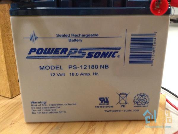
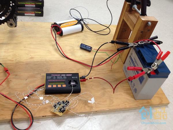
确保骑车时电池不要晃动——电池里的液体晃动会对产生的电能有影响。
电池在不同场景下输出的电压也不一样,充电时大约是14V,正常使用时大约12.5V,放电时大约11V。当然这些值都会随着电池的老化慢慢减小。当输出电压等于14V的时候,应该让电池放电避免过冲。
http://www.power-sonic.com/images/powersonic/sla_batteries/ps_psg_series/12volt/PS-12180_12_Sept_10.pdf
Step 6: 连接电池和逆变器
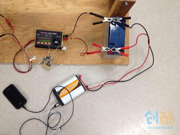
逆变器的选择:输入电压和蓄电池的输出电压一致,输出电压需要与墙上插座的电压一致。输出功率的话,取决于你需要给什么东西充电了。我们这套设备主要是针对学生常用的移动电器,比如手机、笔记本电脑之类的。常见的手机需要5W,电脑需要45~60W。我们选择的逆变器大约有400W的容量。
Step 7: 改善用户体验
因为我们是想把车摆在学生活动中心,所以需要花点心思在用户体验上。一个最大的问题就是充电控制器必需要长按3S钟才能启动工作,我们自己使用倒是没什么可担心的,但放在公共场所,如果有使用者没有背景知识,也懒得读我们写的操作指南的话,一看显示器是亮着的,以为设备已经开始工作了,然后吭哧吭哧骑的满头大汗,结果发现根本就没开始充电。
为解决这个问题,我们稍微改装了一下充电器,用一块arduino来控制开关状态。
Step 8: 改装充电控制器
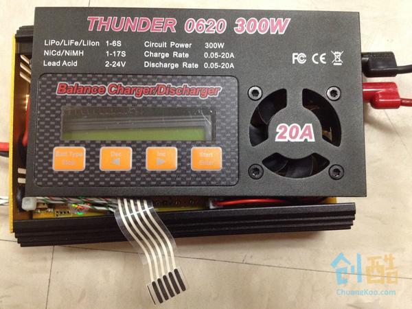
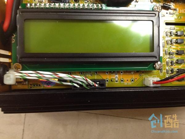
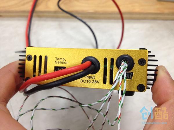
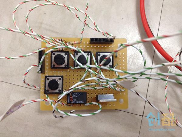

拆开充电控制器,可以看到有一根带状线连着电路板的四个按钮。带状线上有5条引线,一条是基准线,其他四条对应四个按钮。连接基准线和任何一个按钮,就相当于按下这个按钮。所以模拟按钮“长按3秒”也很简单。
在5条引线上分别接一根导线引出来,连到arduino上。
我们在arduino上加了4个按钮,方便测试。还用了一个OMROM G5V-1继电器用于触发开始按钮。电路连接比较简单,可以参考上图。
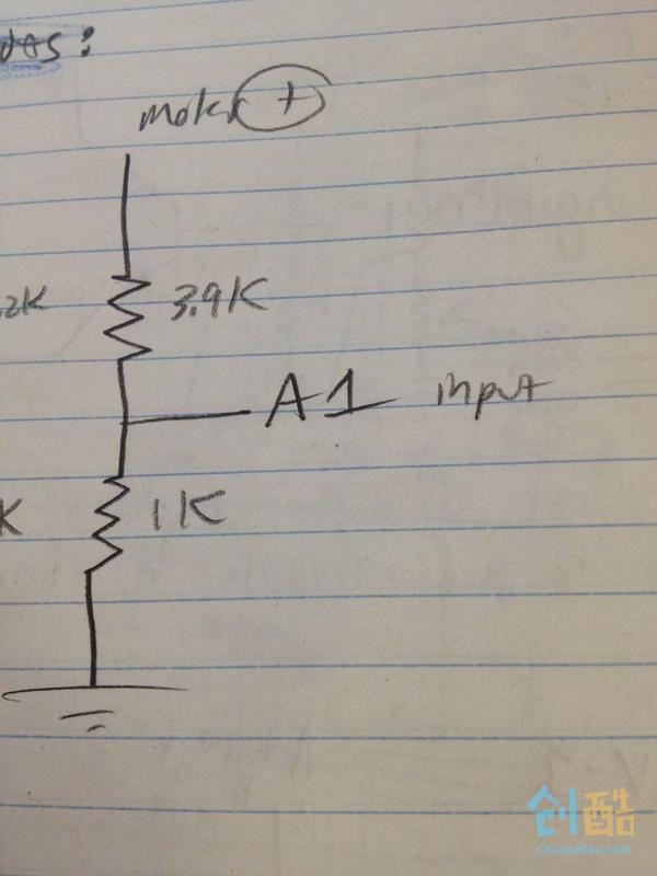
开始按钮可以自动触发了,但是怎么设定触发的条件呢?我们希望当有人开始蹬自行车10S左右的时候,就自动触发开始按钮。那如何检测是否有人在踩自行车呢?有人蹬车的时候,电机就会有电压输出,所以可以用arduino监测电机的输出电压值。因为电机输出电压大于5V,arduino不能直接读到,所以我们加了个分压器,arduino就能读到了。
分压器的原理图如上。用一个3.9K和一个1K的电阻使电机的电压降低为原来的1/5。我们试了下,即使很费劲地蹬自行车,也很难让电机的输出电压超过17V,一般人蹬都超不过15V,所以这个电路应该很安全。
伪代码:
void loop(){
while(!started){

startCharger();

}

void startCharger(){

if (motorVoltage>12 && hasBeenOnForLong){

digitalWrite(relayOut, HIGH); //which really is equivalent to pressing Start
started=true;

}

else if (motorVoltage>12){

//say it has been on for longer

}

else{

//reset hasBeenOnForLong to the beginning

}

}
Step 9: 显示电池电量
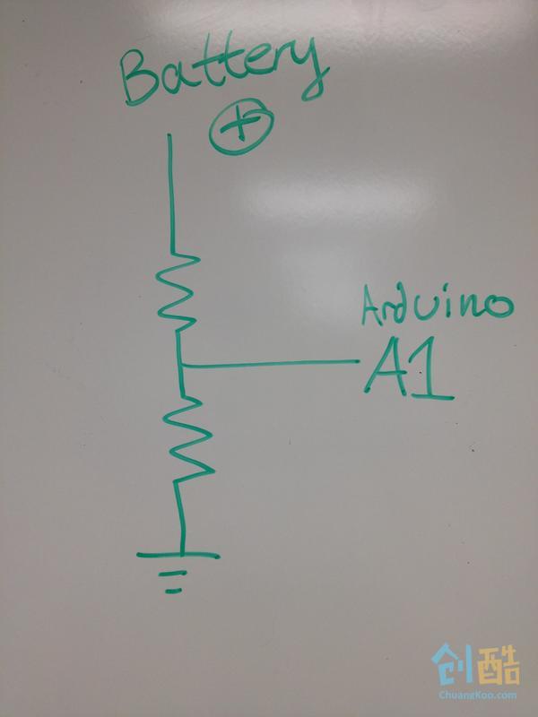
我们需要加个LCD显示屏来显示电池的电量,为此我们用了另一个分压器来测量蓄电池的电压,这样就可以知道电池到底剩多少电。电池的输出电压在14-11V之间,电量和电压之间的对应关系可以参考这儿。http://www.scubaengineer.com/documents/lead_acid_battery_charging_graphs.pdf
因为电池最高输出15V电压,这个分压电路中我们用的是2.2K和1K的电阻,如上图所示。
Step 10: 保存电池电量
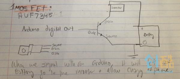
铅酸电池的电量本身就保存的相对比较持久。如果大家只把这套装置当做普通电源,那就没意思了,因此我们想要定写规则,保证使用者必需至少连续骑车两分钟才能开始使用充功能。但是这个功能比较难实现,最后我们在逆变器和电池之间加了个 HUF7345 MOSFET,当MOSFET导通时,手机才可以正常充电。ps:电脑需要的电流比较大,我们担心电池耗尽,只能限制使用者给电脑充电了。
当检测到充电控制器开关按下的时间大于两分钟,我们就把数字输出职位高电平以使MOSFET导通。部分代码如下:
String allowBatteryAccess(){
if(currentMillis-startMillis>(1000*120)){ //if 2 minutes of time has elapsed

digitalWrite(allowBattery, HIGH);

return "Your device has started to charge. Keep Peddling";

}

return " "

}
Step 11: 电路板布局
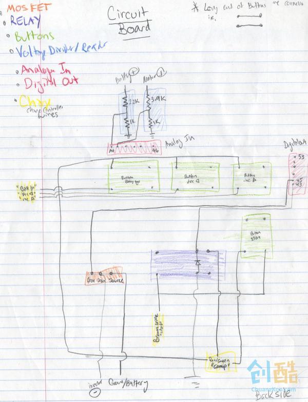
把所有原件焊到一块小板子上,如上图。
附上arduino代码:(未测试)
/* Sallie and Sasha charger programming

*/

// include the library code:
#include <Wire.h>
#include <Adafruit_MCP23017.h>
#include <Adafruit_RGBLCDShield.h>

//PinValues we need to change these
int motorVoltagePin= A0; // voltage output from motor just for fun
int batteryVoltagePin= A1; //voltage of battery that give percent charge
int relayOut=23; //for automatically pressing start button on charger
int allowBattery=24; //for allowing current through the charger

//variables
unsigned long startMillis = 0;
unsigned long currentMillis = 0;
int on = 0;
boolean started = false;
float motorVoltageValue=0;
float batteryPercent=0;
float batteryVoltage=0;

//constants
const float referenceVolts = 5;
const float R1 = 3900; // value for a maximum voltage of 30 volts
const float R2 = 1000;
const float RB1 = 2200; // value for a maximum voltage of 15 volts
const float RB2 = 1000;
const float resistorFactorA = 1023.0 / (R2/(R1 + R2));
const float resistorFactorB = 1023.0 / (RB2/(RB1 + RB2));


void setup(){
   Serial.begin(9600);
}

void loop(){
  while(!started){
    startCharger();
    startMillis = millis();
  }
  Serial.println("You've Started the Charging");
  Serial.println("The voltage you are generating is this:");

  Serial.println("The battery is charged this many %");
  Serial.println(batteryVoltagePercent());
  Serial.println(allowBatteryAccess());
}

String allowBatteryAccess(){
  if(currentMillis-startMillis>(1000*120)){  //if 2 minutes of time has elapsed
    digitalWrite(allowBattery, HIGH);
    return "Your device has started to charge. Keep Peddling";
  }
  return "";
}

void startCharger(){
  Serial.println("Keep pedaling to start charging");
  motorVoltage();
  if((motorVoltageValue>9) && (on>100)){ //if user has been pedaling at a good speed switch relay on
    digitalWrite(relayOut, HIGH);        //which really is equivalent to pressing Start
    started=true;                        //on the front panel of the charger
    delay(1000);                         //Hold button for a minute
  }
  if(motorVoltageValue<2){ //reset the on value if you stop biking, restart the counter
    on=0;
  }
  if(motorVoltageValue>9){ //if you are actually biking at a good speed increase the on count
    on++;
  }
  digitalWrite(relayOut, LOW);
}

float batteryVoltageRead(){
  int val = analogRead(batteryVoltagePin);  // read the value from the sensor
  float volts = (val / resistorFactorB) * referenceVolts ; // calculate the ratio
   batteryVoltage =volts;  // print the value in volts
  return batteryVoltage;
}

float batteryVoltagePercent(){
  if(batteryVoltage<12){
    batteryPercent=.1;
  }
  if(batteryVoltage<12.5){
    batteryPercent=.2;
  }
  if(batteryVoltage<13){
    batteryPercent=.25;
  }
  if(batteryVoltage<13.5){
    batteryPercent=.6;
  }
  if(batteryVoltage<14){
    batteryPercent=.8;
  }
  if(batteryVoltage<15){
    batteryPercent=1;
  }
}

//say we have a max of 24 volts coming from the motor, we want to scale that down by a factor of 5
//to make sure our arduino can read it (it can read 0 to 5 volts) thus we make a voltage divider where R1
//is four times as large as R2 so the voltage is 1/5 of the read out of the motor.  We want a small load
//so we make our resistors very large
float motorVoltage(){
  int val = analogRead(motorVoltagePin);  // read the value from the sensor
  float volts = (val / resistorFactorA) * referenceVolts ; // calculate the ratio
   motorVoltageValue =volts;  // print the value in volts
  return motorVoltageValue;
}
Step 12: 进度&后续打算
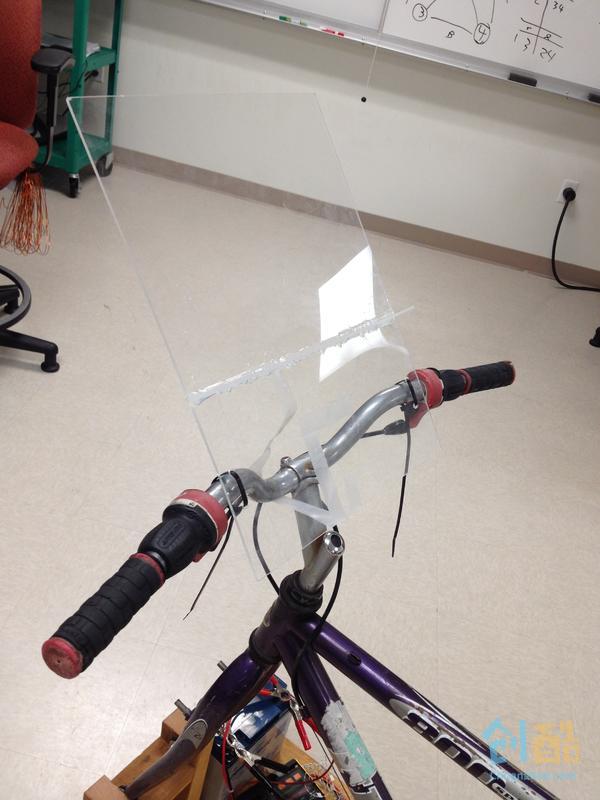
目前arduino那部分功能还没完成,代码也没测试,努力ing。。。
这部分功能完成后,我们可能会在用户交互上多花点功夫。毕竟要把它放在学生活动中心,还是需要吸引大家的好奇心,同时保证安全。我们想在车上装个能和使用者互动LCD显示屏,可以很直观的看到自己产生了多少电能。此外,我们还在车前头装了块有机玻璃,学霸们可以把书搁上面,写写作业啥的。。。
登录以发表评论
哈哈,不错呀。能放到自行车上去,就可以实用啦。不过自行车得改结构了
相当严谨周到,赞!
哈哈,这家伙用的电机我也有一个!一模一样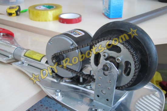

是直流带碳刷的电机么?
回复 fxyc87 : 没错


