会发光的鞋!
标签:Teensy NeoPixel DIY 改装
弹力女超人 发布于 2016-09-09 23:42

2个Teensy 2.0微控制器
Adafruit NeoPixel 数码RGB LED灯带
4个Flexiforce 压力传感器(100lbs)
2个4*AA 碱性电池组 或 2个3*AAA可充电的镍锌电池组
4个1N4001二极管(用4*AA 碱性电池组时才要用到它,如果你用可充电电池,则不需要它)
2只厚底鞋
2个1000uF电容
4个1M的电阻
2个10k的电阻
防水强力胶、焊烙铁 焊锡、绝缘胶带、针线包
(via instructables)
Step 1: 在鞋上粘贴LED灯带
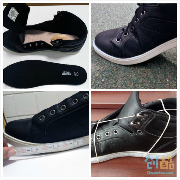
首先准备好你要DIY的鞋!讲真,只要鞋底够厚,鞋内垫能拿出来的鞋都可以,传感器要装在又硬又平的没有鞋垫的鞋内侧。
如果鞋是穿过的,那么在粘NeoPixel之前,要先清理下。一点点灰尘或脏东西都可能会影响粘贴的过程。虽然不一定非要绝对无尘,但是要确保没有任何的小颗粒。
我们的目标是用NeoPixel灯带围鞋粘一圈,但是因为要沿着设计好的切割点切开,它可能不能很完美的适合这个长度,所以最好从鞋的脚后跟的位置开始逆时针环绕。这样,可能产生的小空隙就没有那么明显啦!
接下来用防水强力胶把Neopixel粘到鞋上。每次只粘几寸,这样随时调整,确保粘的好看些。注意,千万不要在鞋弯曲最多的地方(脚掌)粘上胶,这样在你走路的时候,这个部位可以松弛,不会破坏Neopixels
在等待胶水晾干的时候,可以用橡皮筋固定NeoPixel。
Step 2: 给Teensy编程
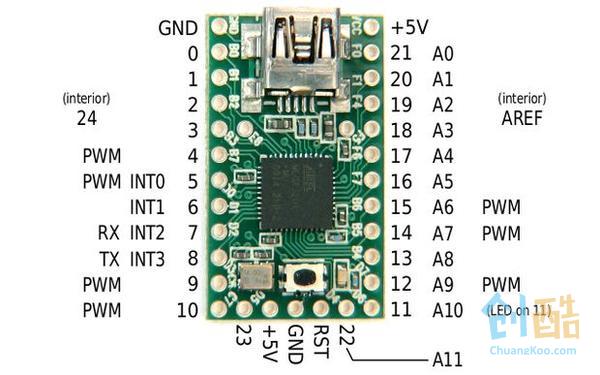
Teensy能与Arduino完全兼容,还可以选择自动安装很多库,包括这个项目要用的Adafruit ones。
一定要有Adafruit NeoPixel 库。
根据你鞋上的LED的数量编辑"int nLEDs = 20;" 还可以修改“int color”这部分,改变默认的LED的颜色
你可能需要看看Teensy 2.0各管脚的电路,这样就知道Teensy是如何与各部分代码连接的
=======以下是代码======
//thanks to Adafruit for the example RGB LED code and libraries

#include "SPI.h"
#include "Adafruit_NeoPixel.h"
/**********************************************/

// Number of RGB LEDs in strand:
int nLEDs = 20;

// Chose a pin for output; can be any valid output pin:
int dataPin  = 15;

//make an instance of the strip object
Adafruit_NeoPixel strip = Adafruit_NeoPixel(nLEDs, dataPin, NEO_GRB + NEO_KHZ800);

//runs on power on
void setup() {
  // Start up the LED strip
  strip.begin();

  // Update the strip, to start they are all 'off'
  strip.show();
}

//repeats while on
void loop() {
  //read the front(A0) and back(A1) force sensor values
  int forceReading1=analogRead(A0);
  int forceReading2=analogRead(A1);

  //iterate throught the LEDs(only half way because the shoe is a mirror image
  for (int i=0; i < strip.numPixels()/2; i++) {
      //set the current LED and its mirrored pair to a combination of the front and back force sensor readings, proportional to their distance from each sensor
      strip.setPixelColor(i, getColorFromForce((forceReading1*i+forceReading2*((strip.numPixels()/2)-i-1))/10));
      strip.setPixelColor(strip.numPixels()-i-1, getColorFromForce((forceReading1*i+forceReading2*((strip.numPixels()/2)-i-1))/10));
    }
    //send the new colors to the strip
  strip.show();
}

//helper function that shifts and scales the force reading to a range of 0-384(for the color wheel function)
uint32_t getColorFromForce(int force){
  //the shift and scaling factors were found experimentally
  int color=(force-350)/1.3;
  if (color>350){
    color=350;
  }
  else if (color<0){
    color=0;
  }
  //return the color that matches the force
  return Wheel(color);
}

//Input a value 0 to 384 to get a color value.
//The colours are a transition b - g -r - back to b
uint32_t Wheel(uint16_t WheelPos)
{
  byte r, g, b;
  switch(WheelPos / 128)
  {
    case 0:
      b = 127 - WheelPos % 128;   //blue down
      g = WheelPos % 128;      // Green up
      r = 0;                  //red off
      break;
    case 1:
      g = 127 - WheelPos % 128;  //green down
      r = WheelPos % 128;      //red up
      b = 0;                  //blue off
      break;
    case 2:
      r = 127 - WheelPos % 128;  //red down
      b = WheelPos % 128;      //blue up
      g = 0;                  //green off
      break;
  }
  return(strip.Color(r,g,b));
}
Step 3: 搭建电路
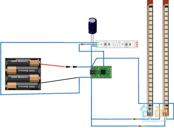
根据电路图用烙铁焊接,还要用热缩管保证连接的可靠性
把压力传感器焊到1M电阻上时,要注意焊接的顺序。电线要同时连着电阻和Teensy的A0/A1端,否则传感器是绝对不会工作的!我不太会同时将3个东西焊在一起,也做了很多次尝试,我也不明白为什么这样就不行。
如果你用4*AA碱性电池组,那么就还需要用2个14N001二极管降低电压输出。我的电路没有装二极管时,输出是6.5V,这有可能会烧了Teensy和Neopixels!!!Teensy2.0需要4.5V-5.5V的电压,也不能过热。有了这两个二极管,电路的电压大概就可以控制在5.55V。
Step 4: 安装所有的东西
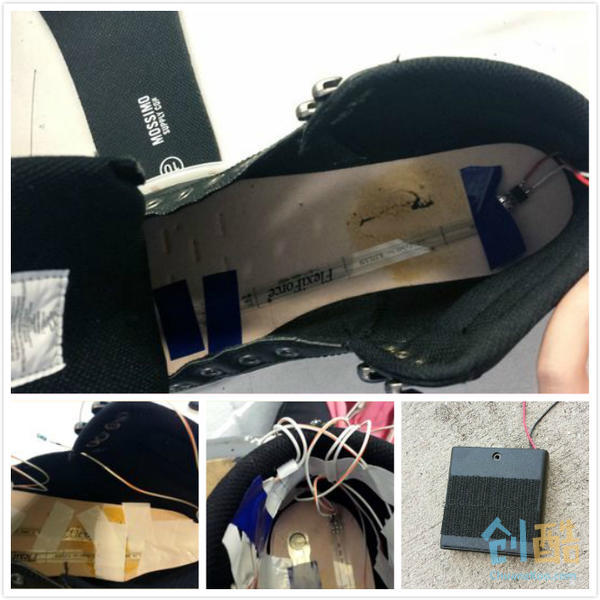
我用胶带把压力传感器固定在鞋里。虽然不好看(如果你像我一样笨手笨脚的,肯定不会好看),但效果不错。
一定要把传感器连到Teensy的A0/F0脚,并且传感器的头要在脚后跟的位置,这样灯就是从脚趾开始亮。我图片中的装反了,灯是从脚后跟开始亮的。你可以自己决定从哪里开始亮
最好,我们要用尼龙搭扣把电源装在鞋舌上:把尼龙搭扣的一边缝在鞋舌上,另一边用能粘合的胶布粘在电池盒上
安装时,我走了一些弯路,也想和大家分享一下:
1. 我大多数都是用胶带粘,但回想起来,这么做不太好,用胶带粘传感器没问题,但是那些乱七八糟的线,最好还是把它们缝在鞋内侧的边上,看着会整齐很多。
2. 我Teensy装在了鞋外侧的脚后跟的位置,太容易坏了!我还是建议把Teensy缝在鞋上(最好在鞋舌头的内侧)。把它焊完后,Teensy上会有大量的空间,能够穿针引线
Step 5: 打开吧!
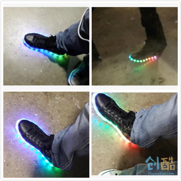
效果是不是很酷!


